
|
Acura Spa Systems, Inc. 2954 Rubidoux Blvd. Riverside, CA 92509 www.acuraspa.com 951-684-6667 ext. 223 sales@acuraspa.com |
|
|
Not All Spa Controls Are Created Equal!!! |
|||||
|---|---|---|---|---|---|
|
Be a smart shopper, know what you are getting for your money!
Ask the salesman to show you whats 'under the hood' by opening the control box! |
|||||
|
|
||||
|
Problem (1): Power Terminal Block Soldered Directly on PC Board Typical failures occur when the incoming power is connected directly on the PC board. The PC board must be replaced at hundreds of dollars. 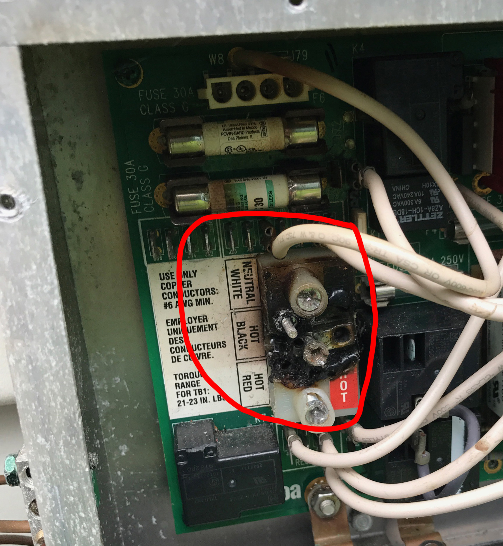
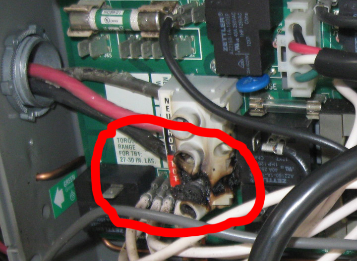
Solution (1): Installing the Power Terminal Block separate from the PC board. If the Power Terminal Block burns due to voltage fluctuations on the power line, the repair can be done by simply replacing a $20 Power Terminal Block, not the entire PC board for hundreds of dollars. |
MT Series - Lowest Operating Costs 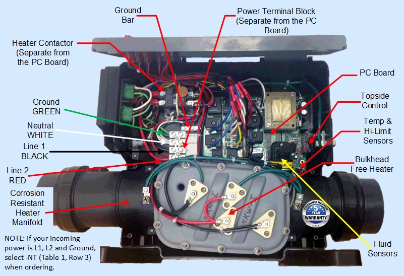
Operates up to 11,000 Watt Heater and up to 5 Pumps USC Series - Low Operating Costs Replaces All Controls With 15" Heater Manifolds 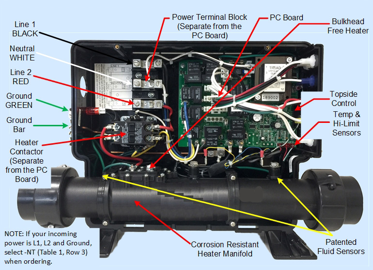
Operates up to 5,500 Watt Heater and up to 5 Pumps CSC Series - Low Operating Costs Replaces All Controls With 15" Heater Manifolds 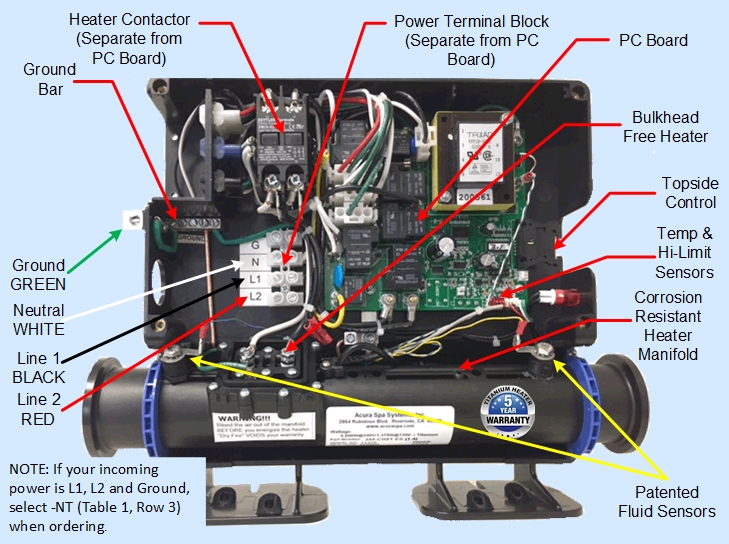
Operates up to 5,500 Watt Heater and up to 1 Jet Pump, 1 Circ. Pump and 1 Blower PM Series - Low Operating Costs Replaces All Controls With 15" Heater Manifolds 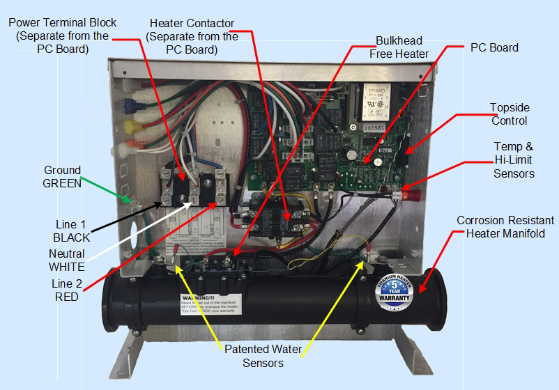
Operates up to 5,500 Watt Heater and up to 4 Pumps |
||||
|
Problem (2): Heater Load is Carried by Relays That Are Soldered Directly on the PC Board Typical failures occur when the heater load is directly connected to the PC board. Once again, the PC board must be replaced at high $ cost. 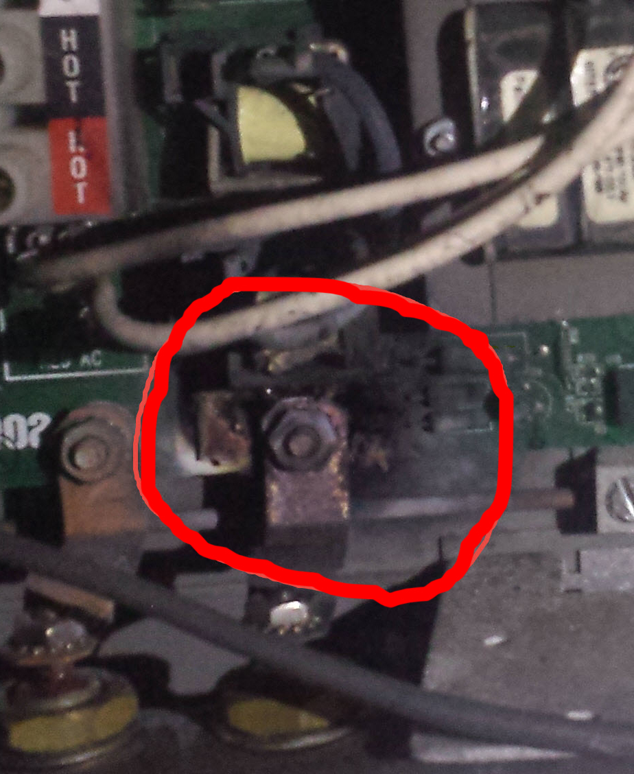
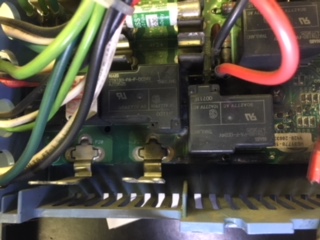
Solution (2): Since 1984 we have used separate and heavy duty contactors to carry the ON/OFF loads of the heaters. Very seldom does a contactor fail; and if it does, since it is separate from the PC board, it only cost $40 to replace. In addition, all relays are energized at Zero Crossing to minimize electrical spikes. |
|||||
|
Problem (3): Heater with Bulk-Heads and 304 Stainless Steel Manfiold Typical failures occur on this style of heater with bulk-heads where the bulk-heads are braised or welded or crimped and epoxied and the heater manifold is made out of 304 stainless steel. 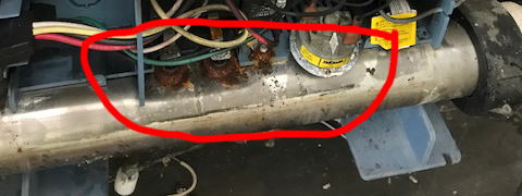
Solution (3): Our patented CosmoHeat with O-ring seals, no bulk-heads, no braising, no welding, no crimping, no epoxy and no 304 stainless steel manifold. Click to see why our bulk-head free heater is the best. Click to see why our heater manifold is the best. Click to see why our submersible heater is the safest in the industry. |
|||||
|
Problem (4): Over-Loaded Single Common Power Relay Typical failures occur when operating two pumps on a single common relay soldered on the PC board. The common relay cannot carry both inductive loads for very long. 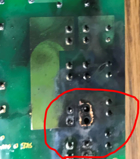
Solution (4): We use two separate common relays to operate two water pumps. In addition, all relays are energized at Zero Crossing to minimize the peak load from the motor on the relay contact points. |
|||||
|
Problem (5): Crowded Circuitry to Reduce Size and Cost Control circuitry is too crowded. Not enough real estate inside the Control Box with too many wires. 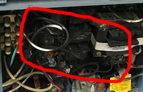
Solution (5): All our circuit traces on the PC boards are properly separated at ⅛" between the AC and DC power lines. We use the proper gauge wires for all circuit loads. All wires that carry AC Power Signals are separated from DC signals on the PC Board to minimize noise and odd software logic glitches. In addition, we maintain a proper ground bus throughout the entire control box. |
|||||